Projected Capacitive Touch Technology
June 2010
Touch screens are becoming increasingly critical in more and more embedded applications, such as industrial control systems, transportation systems and others. According to Display Search industry analysts, touch panel revenues were $3.6 billion in 2008. Touch panel revenues expanded in 2009 to reach $4.3 billion and are projected to triple by 2016, reaching a forecast of $16 billion.
Especially in embedded systems, technologies like projected capacitive touch panels are accelerating the adoption of touch technology by enhancing their durability, reliability and overall performance. In particular, projected capacitive technology can be used for touch panels in embedded applications where the harshness of the environment might wreak havoc on older touch technologies, such as resistive touch panels.
Inherent Issues with Resistive Touch Technology
Resistive touch panels, the most common touch panel technology today, have several well known problems. Some of these problems can be minimized by adding additional contact points, but ultimately the weaknesses of resistive touch panels are an inherent drawback of their construction.
Resistive touch panels are built around two parallel layers of conductive Indium Tin Oxide (ITO). Typically, the bottom layer is coated on a rigid material like glass. The top ITO layer, which is the layer closest to the user, is coated onto a flexible material like a thin sheet of polyester film and when the user touches this top layer, the plastic film bends until it contacts the bottom ITO layer. The contact between the two conductive layers alters the resistance of the ITO layers. This change in resistance is used by the touch panel’s controller to determine the location where the two layers touch (Figure 1).
The various types of resistive touch panels are characterized by the number of connections on the ITO layers. The most basic type, a four-wire resistive touch panel, has two contact points on the top layer and two on the bottom layer. These contacts are connected to dedicated inputs on analog-to-digital converters (ADC). Pressing the top layer changes the resistance of the two ITO layers. These changes in resistance, as measured by the ADCs, define the location of the operator’s touch.
Because the top layer is a flexible film, it is susceptible to damage. The sheet can be torn by the user, it can deform over time, it can warp in high or low temperatures and it can be damaged by cleaning materials. Additionally ITO is a relatively brittle material and repeated bending or flexing can create cracks in the ITO. In general, anything that alters the resistance of the ITO layers changes the touch panel’s performance and, in some cases, can cause permanent damage. This is why resistive touch panels have to be recalibrated often and may even fail after suffering only minor damage.
Some of these problems can be mitigated by adding more contact points. For example, an eight-wire resistive touch panel includes an injected reference voltage on both ITO layers. These reference levels help the system self-calibrate, temporarily overcoming problems caused by drift and warp. A five-wire resistive touch panel uses different connection points and drives the lines differently, allowing it to provide even better correction for drift, warp and some level of physical damage.
No matter what scheme is used to drive a resistive touch panel; the root cause of the technology’s problems is the requirement that the top layer be made of a material flexible enough to be easily depressed by the user. These flexible materials are inherently susceptible to physical damage, which affects the performance and effective life of the resistive touch panel.
Resistive touch panels also degrade LCD visibility. This is due to the fact that the top layer polyester film and the bottom layer ITO glass layer are separated by an air gap. This gap causes internal light reflections. In direct sunlight resistive touch panels can cause the LCD to be unreadable.
Projected Capacitive Touch Panel Technology
Projected capacitive touch panels are also built with two parallel layers of ITO, but, unlike resistive touch panels, the ITO layers in a projected capacitive touch panel are sealed between two sheets of glass by an optically clear adhesive. There is no air gap between layers like a resistive touch panel. The patterns on the two parallel ITO layers form a grid of capacitors. The electric fields of these capacitors are projected through the top layer of glass. When the user places a finger near the top surface of the touch panel, it couples with the electric fields. This coupling changes the capacitance of several of the capacitors in the vicinity of the finger. An algorithm converts these changes in capacitance into a location along the X and Y axes of the panel (Figure 1).
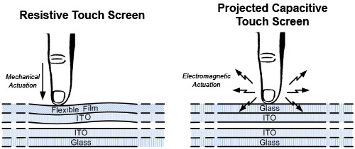
Figure 1
This process involves some high-precision measurements, aggressive noise filtering and complicated algorithms. The change in capacitance is typically in the femto-farad range (10-15 fF). As a result, a dedicated ASIC is needed to amplify, condition and measure the signals. Once the ASIC has determined the changes in each capacitor in the grid, it uses this information to calculate the centroid of the user’s finger. Typically, the position can be resolved to one part in one or two thousand.
The projection of an electric field truly differentiates projected capacitive touch panels from resistive. Since the user is interacting with an electric field, there is no need for the two ITO layers to make physical contact or for the user to make an electrical connection with the touch panel. As a result, the ITO, the contact ledges on the touch panel, the ASIC and all the other sensitive electronics that make up a projected capacitive touch panel can be protected by a top sheet of glass or plastic. Furthermore, the front bezel can be sealed around the edges of the touch panel, creating a completely sealed enclosure. The touch panel can even be bonded to a clear acrylic section of the enclosure (Figure 2), creating a completely smooth top surface.
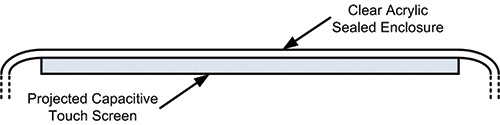
Figure 2
Another advantage of projected capacitive touch panels over resistive is that because the ITO layers are printed on glass, they don’t deform over time. The capacitors built into the ITO layers are always in the same place and the touch panel never needs to be re-calibrated.
From an optical standpoint, the projected capacitive touch panel is far superior. Since there are no internal air gaps, internal light reflections are very minimal and the visibility of the LCD is largely unaffected by lighting conditions.
Keeping the Gloves On
As a result of environmental conditions, operators of some embedded applications may wear gloves when interacting with a touch panel. Resistive touch panel technology works well in these types of applications since it doesn’t matter what interacts with the panel. All that matters is whether the ITO layers contact each other. For a touch to be detected on a projected capacitive touch panel something has to alter the capacitive fields in the ITO layers. Gloves may or may not work with projected capacitive technology depending on the thickness of the glove, the type of material, and the sensitivity of the touch panel. For example, thinner gloves, like surgical gloves, usually work well while heavy winter gloves do not.
Some of these problems can be overcome by adjusting the sensitivity of the projected capacitive touch panel. For example, if the touch panel is always going to be used in a cold environment, the sensitivity can be increased so that it can detect fingers through a thick glove. However, this can also make it difficult to operate the touch panel without gloves.
A projected capacitive touch panel can also be designed to work with an active stylus (that is, a stylus that is electrically attached to the system). A good example of this is a credit card reader with a stylus for capturing signatures. Using a stylus greatly improves the accuracy of the touch panel. However, the stylus must be physically connected to the system to work properly. The good news with projected capacitive touch panels is that in applications like signature capture, the stylus only touches the top glass surface. Millions of names can be signed on the glass without damaging the touch panel.
Multi-Touch and Advanced Gesturing
Due to the method used to determine the touch location in projected capacitive touch panels, it’s possible to detect multiple touches simultaneously. When multiple fingers are placed on a projected capacitive panel, a two-dimensional “sheet” of changes in capacitance values is created (Figure 3). When the entire sheet is analyzed, the peaks in the sheet are associated with touch locations. Using this technology, multiple touch points can be identified. It is also possible to analyze finger movements and identify specific gestures like pinching (zoom-out), stretching (zoom-in) and swiping (left, down, up, right, sideways and others). Thanks to the tremendous popularity of touch screen smartphones, this type of advanced gesturing is becoming widely adopted as the standard way users interact with technology today.
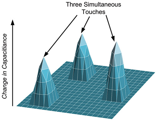
Figure 3
While features like multi-touch and gesturing can be accomplished in software by the touch panel driver, they are very math intensive and time consuming. The newest projected capacitive touch panel controllers can interpret the touch data and generate gesture events directly, greatly simplifying the application software.
Deployment in Embedded Applications
As a result of the success of the advanced smartphones, consumers have discovered the many benefits of projected capacitive touch panels. In particular, people are realizing that the gesturing interface used on the advanced smartphones is a natural way of interacting with electronic devices. Now that projected capacitive touch panels are available in larger panel sizes (Figure 4), designers can bring this same experience to a variety of embedded systems where the durability, reliability and overall performance of this technology can also add substantial value to the system.
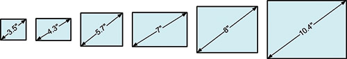
Figure 4
Contact Us for more information.